The use of an electric contact pressure gauge
Electric contact pressure gauge (signalling) for water supply systems. Principle of operation, application, design, marking and types.
Ensuring pressure control in water supply systems and systems of a similar type is a necessary component for the normal operation of water supply systems. There are equipment options that solve this problem by providing control of the system components, including the pump. For this purpose, a pressure switch or an electrocontact pressure gauge is used. In this article, you can learn about the nuances of the pressure switch and proximity switch, the advantages and disadvantages of each.
Advantages and disadvantages of the electrocontact pressure gauge in relation to the pressure switch.
The advantage of the electrocontact pressure gauge is that it is assembled in a single housing for the switching contacts and the control pressure gauge. This is convenient because this design does not require additional tees for assembly. Although you can find a version of the pressure switch that has a built-in pressure gauge. Perhaps one of the main advantages of the pressure gauge is the ease of setting up the device and accurate visualisation of the triggering limits by pressure readings. The design of this type of pressure gauge allows you to set the lower and upper limits at which the mechanism will be triggered. This is achieved without the use of special keys, only with the help of contact arrows. In this case, we get a visual setting of the pressure gauge. Relays do not have this capability.
The disadvantages of the electrocontact pressure gauge are low switching currents, on average 0.3-0.5 A. This does not allow you to connect powerful devices without additional equipment. For this purpose, powerful relays are used, which, in turn, require an additional power supply.
This feature is the reason why the electrocontact pressure gauge is called a signalling gauge. When changes occur, it signals about them, and a power relay serves as the actuating device.
The second disadvantage of this pressure gauge is its high cost relative to pressure switches. On average, the price can differ by 2-3 times not in favour of the pressure gauge.
The field of application of the signalling pressure gauge is heat supply, water supply, ventilation systems, mechanical engineering, etc.
In particular, they are widely used to switch on pumping stations that supply water.
General information about the electrocontact (signalling) pressure gauge.
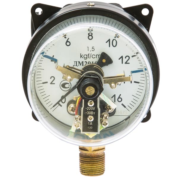
The electrocontact pressure gauge is used to determine the overpressure of the working medium. The measured medium must be non-aggressive, non-crystallising (liquid, steam, gas, including oxygen). These are devices with an electrical contact group.
When a certain upper and lower pressure limit is reached, the pressure gauge mechanism triggers the contact group. Using additional arrows on the scale of the device, you can set the pressure ranges – minimum and maximum – that correspond to the closing points of the electrical circuit. These switching modes are used to control electrical circuits. When the medium pressure crosses the limit arrows, the contacts of the electrical circuit open or close.
Different contact groups can be used depending on the type of pressure gauge.
Information about the contact groups is given below.
Connecting an electrical contact (signalling) pressure gauge.
Depending on the scope of application, conditions and purpose, different types of ECM pressure gauges are used, which have different modifications of electrical circuits:
Type 1 – single-contact closing type;
Type 2 – single-contact open circuit;
Type 3 – two-contact open-open switch;
Type 4 – two-contact closing-opening;
Type 5 – two-contact contact for opening and closing;
Type 6 – two-contact open-close switch.
(For clarity, the following is a diagram of the possible switching groups in the wiring diagram for pressure gauges types 3 to 6)
The signalling device can be of different versions:
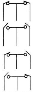
III – both contacts are open. The left pointer (min) is blue, the right pointer (max) is
red.
IV – both contacts are closed. Left indicator (min) red, right indicator (max)
blue.
V – one contact is open (min), the other is closed (max). Both indicators are blue
VI – one contact is closed (min), the other is open (max). Both indicators are red.
Note: When the pressure arrow reaches the setpoint of the left or right pointer, the contact is opened (closed).
There are accepted standards for colour coding of signalling devices.
The standards for colour marking of the switching wires of electrocontact pressure gauges during manufacture and also during connection are as follows:
blue – minimum
red – maximum;
yellow – common.
The principle of operation of an electrocontact (signalling) pressure gauge.
The principle of operation of electrocontact pressure gauges is based on the fact that when the pressure level reaches a certain set point, the built-in contact group is opened or closed by a movable contact, which is an arrow, and the built-in contact group is triggered. The closing or opening of the electrical circuit depends on the type of device. Such a wide range of capabilities of electrocontact pressure gauges allows them to be widely used in various industrial areas.
All types of electrocontact (signalling) pressure gauges are marked with the technical parameters of the device.
An example of decoding a device marking.
Electro contact pressure gauge DM 2005-U2 (1.0, MPa, ac. 1.5, M20x1.5, IR40, bottom, V)
- 1.0 – measuring range (from 0 to 1.0 MPa);
- MPa – units of measurement
- accuracy class 1.5 – accuracy class
- M20x1.5 – thread of the connecting fitting
- IP40 – degree of protection
- Bottom – location of the connector (radial)